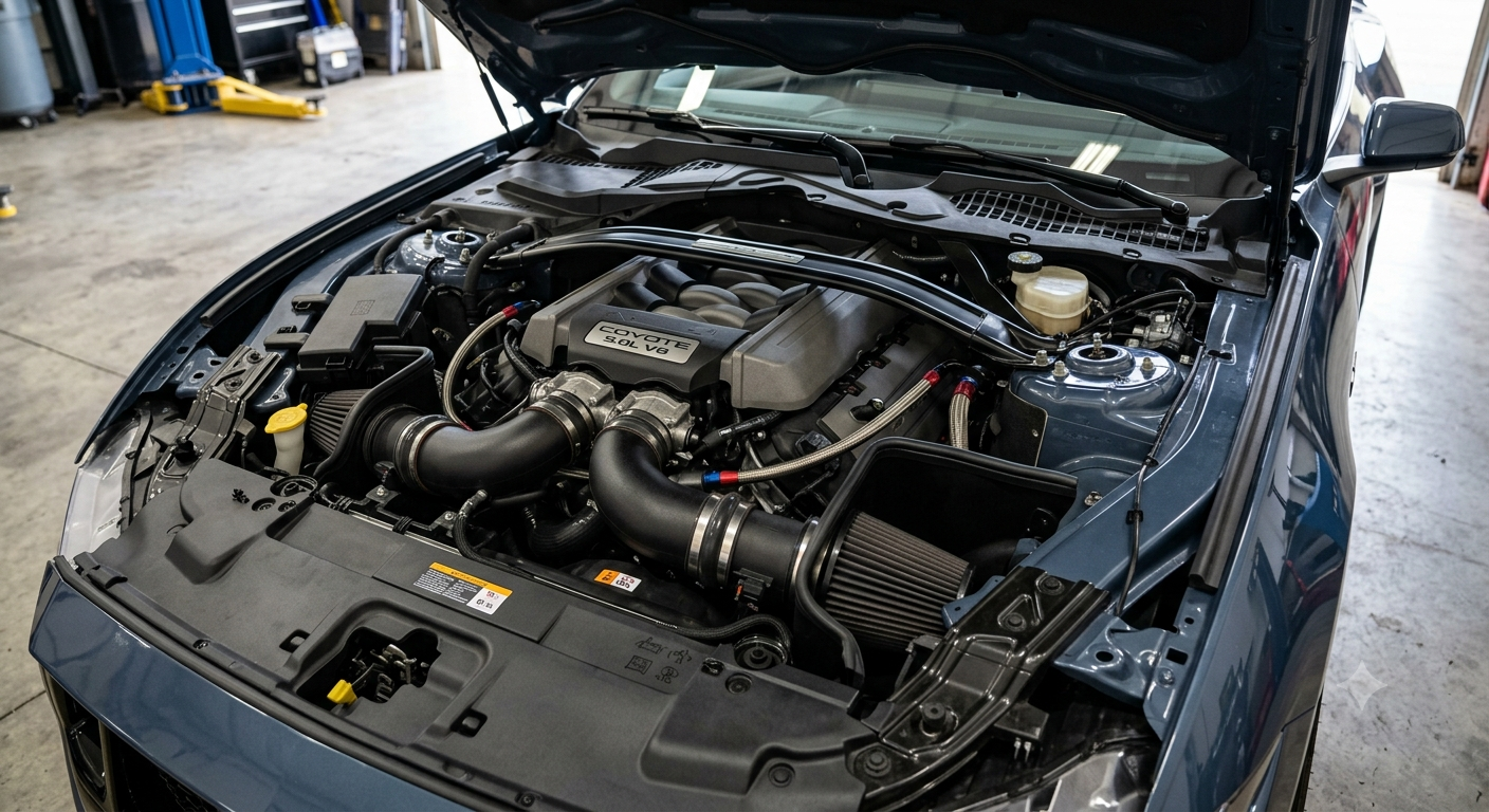
The Ford Mustang has evolved from a straight-line muscle car into a sophisticated high-performance sports car platform. achieving this level of mechanical precision requires deep technical integration between thermodynamics, forced and natural induction, electronic chassis controls, and aerodynamic package design.1. Powertrain Architecture & Combustion Engineering
At the heart of the Mustang platform are two distinct combustion strategies: the turbocharged 2.3L EcoBoost inline-4 and the naturally aspirated 5.0L Coyote V8. Both engines leverage distinct thermodynamics and fluid flow dynamics to balance volumetric efficiency with thermal limits.
The 5.0L Coyote V8 (Fourth-Generation Architecture)
The 5.0L Coyote utilizes a 90-degree aluminum block featuring a bore of 93.0 mm and a stroke of 92.7 mm, producing a displacement of 5,038 cc with a high static compression ratio of 12.0:1.
- Dual-Intake Throttle Body Configuration: Modern revisions incorporate a dual-throttle-body intake system fed by twin induction runners. This layout significantly reduces intake air throttling losses and improves air mass flow rates at high engine speeds (exceeding 7,000 RPM).
- Dual-Fuel Injection Strategy: The engine operates a hybrid direct-injection (DI) and port-fuel-injection (PFI) system. Under low-to-medium loads, PFI ensures optimal air-fuel mixing and minimizes particulate generation. At high load demands, the high-pressure DI system injects fuel directly into the cylinder chamber at pressure up to 250 bar (3,625 psi), utilizing the latent heat of vaporization to cool the intake charge and suppress detonation (engine knock).
- Variable Cam Timing (Ti-VCT): Twin Independent Variable Camshaft Timing employs oil-pressure actuators to retard or advance intake and exhaust valve timing independently. This optimizes cylinder fill efficiency across the torque curve without sacrificing high-end horsepower.
The 2.3L EcoBoost Inline-4
The 2.3L EcoBoost relies on high charge density achieved via forced induction:
- Twin-Scroll Turbocharging: By separating exhaust pulses from cylinders 1-4 and 2-3 into distinct turbine scroll channels, exhaust gas scavenging is maximized. This reduces backpressure, accelerates turbine spool-up, and minimizes turbo lag down to 2,000 RPM.
- Integrated Exhaust Manifold: The cylinder head incorporates an integrated exhaust manifold cast directly into the head structure. Liquid engine coolant passes around the exhaust ports, reducing exhaust gas temperatures before reaching the turbine, which preserves turbocharger durability under sustained wide-open throttle (WOT) operation.
2. Dynamic Heat Dissipation & Thermal Management
Sustaining high mechanical load on track environments requires advanced fluid cooling and airflow direction:
| Component | Engineering Implementation | Primary Technical Function |
| Engine Oil Cooler | Air-to-liquid heat exchanger integrated into radiator loop | Prevents viscosity shear breakdown during high oil thermal stress |
| Transmission Cooler | Dedicated auxiliary radiator with forced-air shrouding | Keeps transmission fluid below critical fluid breakdown thresholds |
| Rear Differential Cooler | Axle-mounted fluid pump and exterior heat exchanger | Mitigates thermal expansion and gear wear under torque vectoring loads |
| Brake Cooling Ducts | Molded bumper channels directing high-pressure air | Reduces rotor thermal fade by dissipating kinetic energy |
3. Drivetrain & Transmission Kinematics
Power transfer from the crankshaft to the rear drive wheels demands minimal mechanical power loss and precise torque modulation.
Getrag MT-82 6-Speed Manual vs. 10-Speed SelectShift Automatic
- Manual Transmission (MT-82): Employs twin-disc clutches to minimize rotational inertia. The manual linkage features integrated active rev-matching technology, which reads sensor data on gear selector position and driveshaft speed to blip the electronic throttle body, perfectly matching engine RPM to transmission input shaft speed during downshifts.
- 10-Speed SelectShift Automatic (10R80): Utilizes real-time adaptive shift scheduling algorithms. The system processes driver inputs, vehicle inclination, lateral G-forces, and throttle rate every 10 milliseconds. Wide ratio spans (7.38:1 total spread) allow optimal engine operation within the peak power band, while direct clutch-to-clutch transitions reduce shift latency down to sub-100 millisecond intervals.
Torsen Limited-Slip Differential Mechanics
For high-performance variants, a helical-gear Torsen limited-slip differential manages torque bias across the rear axle. Unlike traditional clutch-pack differentials that rely on friction plates, the Torsen unit utilizes worm gears to sense torque balance mechanically. When an outside wheel gains traction over an inside slipping wheel, the differential automatically multiplies input torque to the gripping wheel based on its designed Bias Ratio (typically 2.5:1 to 4:1) without electronic intervention delay.
4. Chassis Dynamics, Suspension Geometry, and Electronics
The S550 and S650 platforms transitioned from legacy live rear axles to fully independent rear suspension (IRS), completely restructuring the vehicle’s handling characteristics.
Front Suspension: Double-Ball-Joint MacPherson Strut
Rear Suspension:  Integral-Link Independent Rear Suspension (IRS)
Damper Control:   MagneRide Damping System (Magnetorheological Fluid)
Suspension Geometry Engineering
- Front Double-Ball-Joint MacPherson Strut: Splitting the lower control arm into two separate links with individual ball joints creates a virtual steer axis. This setup reduces the scrub radius, yields tighter turn-in feedback, and counteracts torque steer or tramlining tendencies.
- Rear Integral-Link IRS: Aluminum lower control arms, upper camber links, and vertical integral links control toe, camber, and castor under heavy lateral cornering loads. The separation of cornering forces from longitudinal braking forces improves tire contact patch retention across uneven pavement.
MagneRide Damping System
The semi-active MagneRide suspension alters shock absorber damping characteristics instantaneously:
$$\text{Viscosity Adjustments} \propto \text{Electromagnetic Field Strength}$$
The damper fluid contains microscopic iron particles suspended in synthetic hydrocarbon oil. An onboard ECU reads vehicle wheel-position sensors, vehicle speed, steering angle, and lateral accelerometers up to 1,000 times per second. By varying the electric current supplied to an internal coil inside the shock piston, the magnetic field aligns the iron particles into microscopic chains, instantly changing the fluid’s viscosity and damping resistance within milliseconds.
5. Aerodynamics and Ground-Effect Physics
Aerodynamic development focuses on balancing a low coefficient of drag ($C_d$) with high localized downforce at high velocities.
- Front Splitter & Air Curtain Ducts: The front splitter creates a localized high-pressure zone above the blade and a low-pressure zone beneath it, generating front axle downforce. Air curtain vents direct high-velocity air around the outer front wheel faces to seal the wheel well turbulence.
- Underbody Paneling: Smooth composite underbody panels minimize aerodynamic drag and prevent air stagnation under the vehicle, allowing clean airflow to feed the rear diffuser.
- Rear Wing & Gurney Flap: The rear wing leverages an inverted airfoil profile. An optional Gurney flap creates a small boundary-layer separation bubble at the trailing edge, increasing total downforce with minimal penalty to top-speed drag profile.
Through integrated mechanical engineering, precise control systems, and aerodynamically efficient designs, the modern Mustang platform maintains its position as an exceptionally capable automotive engineering achievement.
Also Read: The Evolution of the Desktop Inbox: An In-Depth Look at Mailbird – My Tech Blaze
Source: Ford Mustang – Wikipedia