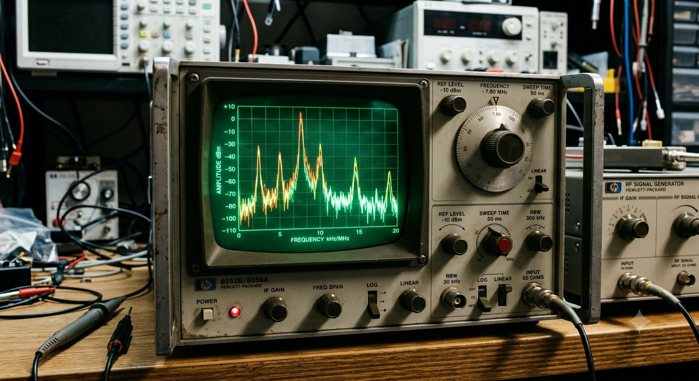
The electromagnetic (EM) spectrum is the fundamental physical medium underlying all modern wireless communication. Ranging from extremely low-frequency radio waves to high-frequency gamma rays, it encompasses a continuous range of frequencies and wavelengths. In telecommunications, spectrum management determines how data is encoded, transmitted, and received across various physical channels. Understanding the structural properties of the spectrum, its operational bands, and the engineering principles behind its utilization is crucial for designing robust, high-capacity wireless networks.
1. Physical Foundations of Electromagnetic Waves
Electromagnetic radiation travels through free space at the speed of light ($c \approx 3 \times 10^8\text{ m/s}$). The fundamental relationship between a wave’s speed, frequency ($f$), and wavelength ($\lambda$) is governed by the wave equation:
$$c = f \lambda$$
As frequency increases, wavelength decreases proportionally. This physical reality directly impacts two core aspects of telecommunications signal behavior:
- Free-Space Path Loss (FSPL): Higher-frequency signals experience greater attenuation over distance. FSPL is mathematically represented by Friis’ Transmission Equation:$$\text{FSPL} = \left( \frac{4\pi d f}{c} \right)^2$$where $d$ is the distance between antennas. Consequently, higher frequencies require denser infrastructure (e.g., small cells) to achieve equivalent coverage.
- Propagation Mechanisms: Low-frequency signals (e.g., Sub-1 GHz) easily diffract around obstacles and penetrate solid building materials. Higher frequencies, such as millimeter waves (mmWave), behave like light: they travel predominantly via Line-of-Sight (LoS) paths and are easily blocked or absorbed by rain, foliage, and concrete.
2. Band Breakdown and Operational Characteristics
The radio frequency (RF) portion of the spectrum spans from roughly $3\text{ kHz}$ to $300\text{ GHz}$. Engineeers categorize this spectrum into operational bands based on propagation dynamics and channel capacity.
| Band Name | Frequency Range | Wavelength Range | Key Telecommunications Applications |
| Very Low Frequency (VLF) | $3\text{ kHz} – 30\text{ kHz}$ | $100\text{ km} – 10\text{ km}$ | Submarine communications, long-range navigation |
| High Frequency (HF) | $3\text{ MHz} – 30\text{ MHz}$ | $100\text{ m} – 10\text{ m}$ | Shortwave radio, over-the-horizon radar |
| Ultra High Frequency (UHF) | $300\text{ MHz} – 3\text{ GHz}$ | $1\text{ m} – 10\text{ cm}$ | Cellular networks (4G/5G), Wi-Fi (2.4 GHz), GPS, Bluetooth |
| Super High Frequency (SHF) | $3\text{ GHz} – 30\text{ GHz}$ | $10\text{ cm} – 1\text{ cm}$ | Wi-Fi 6E/7 (5–6 GHz), C-Band 5G, satellite links |
| Extremely High Frequency (EHF) | $30\text{ GHz} – 300\text{ GHz}$ | $1\text{ cm} – 1\text{ mm}$ | mmWave 5G (24–39 GHz), point-to-point microwave backhaul |
3. Data Throughput and Channel Capacity
The maximum rate at which data can be reliably transmitted over a communication channel is governed by the Shannon-Hartley Theorem:
$$C = B \log_2 \left(1 + \frac{S}{N}\right)$$
Where:
- $C$ is the channel capacity in bits per second (bps).
- $B$ is the channel bandwidth in Hertz (Hz).
- $S/N$ is the Signal-to-Noise Ratio (SNR).
This relationship highlights why access to contiguous bandwidth ($B$) is essential for high-throughput mobile networks.
Spectrum Partitioning in 5G Networks
Modern 5G architectures divide the usable RF spectrum into three primary layers to balance coverage and throughput requirements:
- Low-Band (Sub-1 GHz): Provides broad geographic coverage and deep indoor penetration. Bandwidth availability is limited (typically $10–20\text{ MHz}$ channels), yielding modest data rates ($50–250\text{ Mbps}$).
- Mid-Band ($1–6\text{ GHz}$): Offers an optimal balance of coverage and throughput. The C-Band ($3.7–3.98\text{ GHz}$) provides channel widths up to $100\text{ MHz}$, delivering real-world throughputs between $100\text{ Mbps}$ and $1\text{ Gbps}$.
- High-Band / mmWave ($24\text{ GHz+}$): Offers massive channel bandwidths ($200–800\text{ MHz}$), supporting multi-gigabit throughput ($2–10\text{ Gbps}$). Due to severe attenuation, range is typically constrained to under $500\text{ meters}$.
Frequency Spectrum Allocation Architecture

[ Low-Band: Sub-1 GHz ]   -------->  Max Coverage / Min Throughput
   │
[ Mid-Band: 1–6 GHz ]     -------->  Balanced Coverage & Capacity (C-Band)
   │
[ High-Band: 24–39 GHz ]  -------->  Min Coverage / Max Throughput (mmWave)
4. Modern Spectrum Management and Dynamic Sharing
RF spectrum is a finite resource managed internationally by the International Telecommunication Union (ITU) and nationally by regulatory authorities (e.g., the FCC in the US or TRAI in India). Traditionally, spectrum was allocated via static licensing. However, growing bandwidth demands have spurred the adoption of advanced dynamic utilization strategies:
Carrier Aggregation (CA)
Carrier Aggregation enables mobile network operators to combine multiple distinct spectrum blocks—even across non-contiguous frequency bands—into a single virtual channel. This multiplies available bandwidth ($B$) to increase total throughput.
Dynamic Spectrum Sharing (DSS)
DSS allows operators to run 4G LTE and 5G New Radio (NR) simultaneously within the same frequency band. The network scheduler dynamically allocates spectrum resources in real time based on user traffic demand.
Licensed Shared Access (LSA) and CBRS
Systems like the Citizens Broadband Radio Service (CBRS) in the $3.5\text{ GHz}$ band utilize a three-tiered spectrum access framework managed by a Spectrum Access System (SAS):
- Tier 1 (Incumbents): Military radar and satellite ground stations receive absolute priority.
- Tier 2 (Priority Access Licenses – PAL): Paid users receive interference-protected access when Tier 1 is inactive.
- Tier 3 (General Authorized Access – GAA): Unlicensed users access remaining spectrum opportunistically.
5. Engineering Challenges at Higher Frequencies
Utilizing the upper limits of the RF spectrum introduces key hardware and propagation challenges:
- Phase Noise & Linearity: High-frequency RF power amplifiers operate near their compression points, introducing non-linear distortion that degrades high-order Quadrature Amplitude Modulation (e.g., 256-QAM or 1024-QAM).
- Beamforming: To compensate for severe propagation loss at mmWave frequencies, base stations deploy Massive MIMO (Multiple-Input Multiple-Output) antenna arrays. Phased array architectures adjust signal phases to form concentrated directional beams targeted at individual end-user devices.
Conclusion
The electromagnetic spectrum remains the cornerstone of mobile connectivity and data transmission. As wireless technology transitions beyond 5G toward Sub-THz and terahertz ($100\text{ GHz} – 3\text{ THz}$) regimes for 6G, balancing propagation constraints with channel bandwidth will require continued innovation in antenna arrays, dynamic spectrum sharing algorithms, and RF hardware design.
Also Read: The Ultimate Guide to Modern Cybersecurity: Demystifying Malwarebytes – My Tech Blaze
Source: Spectrum Internet, TV, Mobile & Home Phone | Official Site